
Development
Device Side
LocalTalk
The port itself is known as a LocalTalk. It speaks a variant of RS422 (ie it’s differential transmission). Here’s a pinout of the port, relative to the DCE. It uses a mini DIN-8 plug.
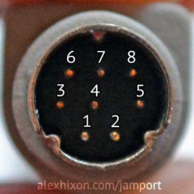 Mini-DIN 8 Male
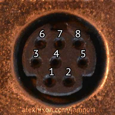 Mini-DIN 8 Female
| Pin | Name | Purpose |
|---|---|---|
| 1 | HSKo | "Handshake out"; used as external clock output, or DTR |
| 2 | HSKi | "Handshake in"; used as external clock input, or CTS |
| 3 | TxD- | Transmit data (negative differential) |
| 4 | GND | Ground |
| 5 | RxD- | Receive data (negative differential) |
| 6 | TxD+ | Transmit data (positive differential) |
| 7 | GPI | Shared GPIO pin |
| 8 | RxD+ | Receive data (positive differential) |
Keep in mind that if you’re relying the pin purposes to work out which lines you need to send or receive data on, don’t forget they are relative to the DCE (‘modem’ side). Don’t do what I did and forget to swap connect TxD to RxD (and vice versa), and instead have the two devices literally shouting at each other and listening to silence.
To take an example, and for my own future reference since I kept making this mistake during development; the DCE’s HSKo pin 1 will connect to the DTE’s (Mac’s) HSKi.
If you’re simply making a cable, you shouldn’t need to (mentally or physically) swap anything!
On GeoPort and LocalTalk
Confusingly, Apple also has a thing called a GeoPort connector. The pinout is the same as LocalTalk, but with the addition of an extra pin (pin 9; +5V power rail). Since it has an extra pin, it uses a mini DIN-9 plug. This means at a hardware protocol level, if it can speak GeoPort, it can speak LocalTalk (but not vice versa).
GeoPort also defines a specific purpose for pin 7, which is used for wakeup/DMA request. Under LocalTalk, the pin’s purpose is defined by a combination of the connected hardware, and the software connecting to the serial port.
On AppleTalk
AppleTalk is just a protocol on top of LocalTalk to provide networking features. Its name is here to confuse you. Ethernet has long replaced it.
Using LocalTalk with RS422 and RS232
The function of HSKi/HSKo/GPIO can be switched depending on the register values inside the SCC (see datasheet), and the software using the serial port.
This is useful if you want to connect it directly to RS422. In this mode, HSKo/HSKi are switched to DTR/CTS mode, and GPI is treated as Carrier Detect.
We can also use RS232 if we only ever talk on the negative side of the differential communication link.
There are details on how build adapter cables on the internet. You can also take a look at Apple Peripheral Interface Guide (March 1989).
There used to be a published Apple note that also contained this information, but I can’t seem to find it any more. They seem to be scrubbing all this useful old information off their website.
Mac side
The key was working out which pins did what on the connector. Don’t ask me how I got this.
 Simplified "Modem Board Connector (Dash II)" circuit diagram
This one’s called the Dash II, according to this specific version of it, but is sometimes generically referred to MicroDash (which, confusingly, can have a different pinout). Note that there are some modem-specific pins we leave unconnected (as they are on other modem-serial adapters).
Bridging The Two
If you look at the Microdash connector pinout, you can see the Mac side is basically RS232 with the extra clocking pins and GPIO pin that’s on the Zilog SCC UART controller. Interestingly, all the newer PowerMacs seem to have the Zilog controller as an IP core inside one of their south-bridge ASIC, rather than as a separate chip). For the ASIC implementation, these appear to speak at or around TTL level (don’t quote me on that, though).
On the device side, we have essentially RS422 with some extra pins (which are not differential). So, really, what we’re trying to do here is make an RS232/ RS422 adapter!
How does the Stealth Port do it? It uses only a single IC — the DS8925 (datasheet) — and some filtering capacitors. The DS8925 is a “single chip” GeoPort transceiver IC from National Semiconductor (now Texas Instruments). Unfortunately, it’s is an obsolete part, so I can’t just build an exact replacement circuit.
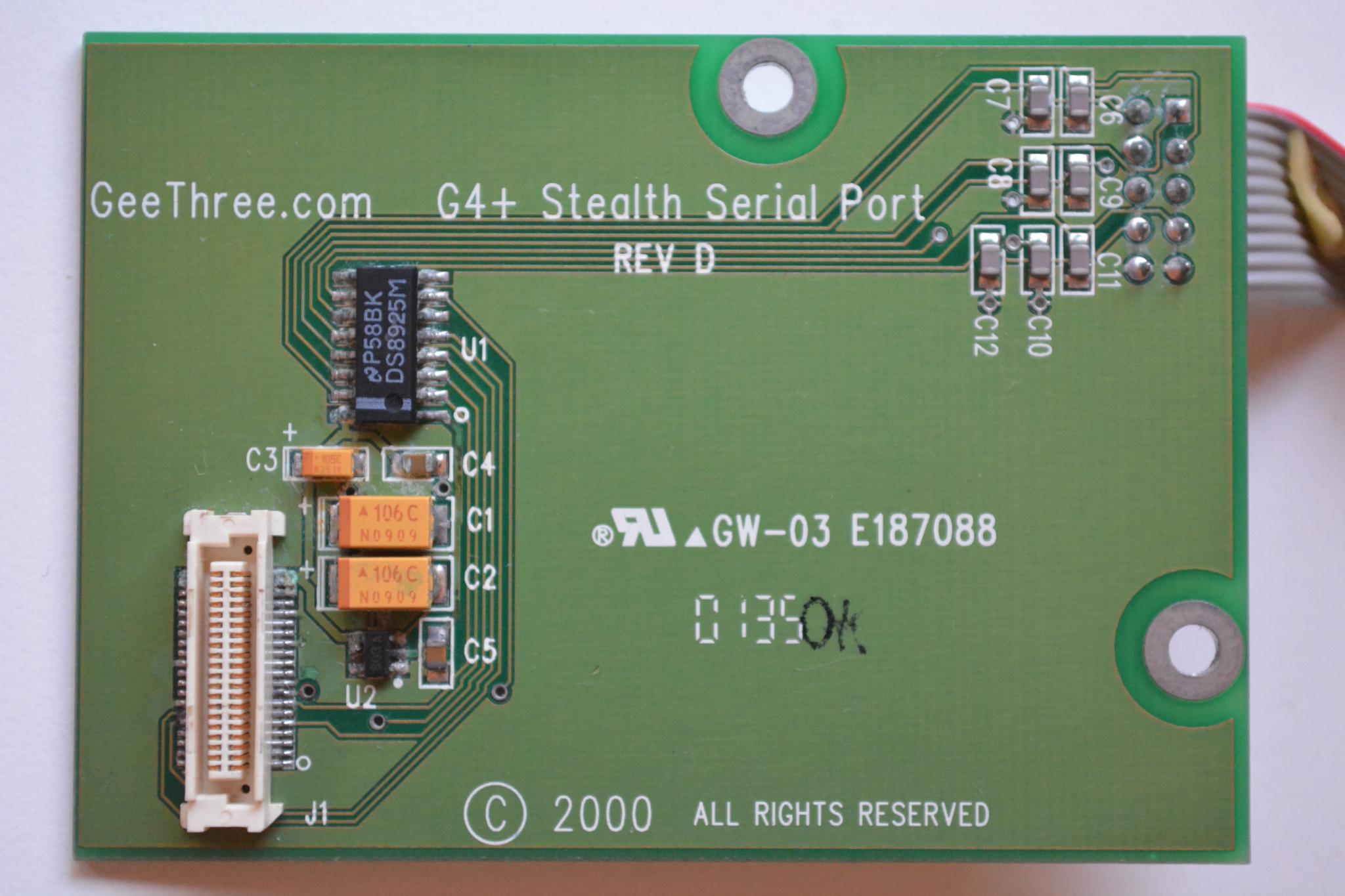 Photograph of the G4+ Stealth Serial Port with DS8925 IC
There are a few similar ICs though, a number of which are obsolete:
- Linear LTC1323
- Linear LTC1318 (obsolete)
- Sipex (now Exar) SP303 (obsolete)
- Texas Instruments SN75LBC771
- Texas Instruments SN75LBC773 (obsolete)
- Texas Instruments SN75LBC776
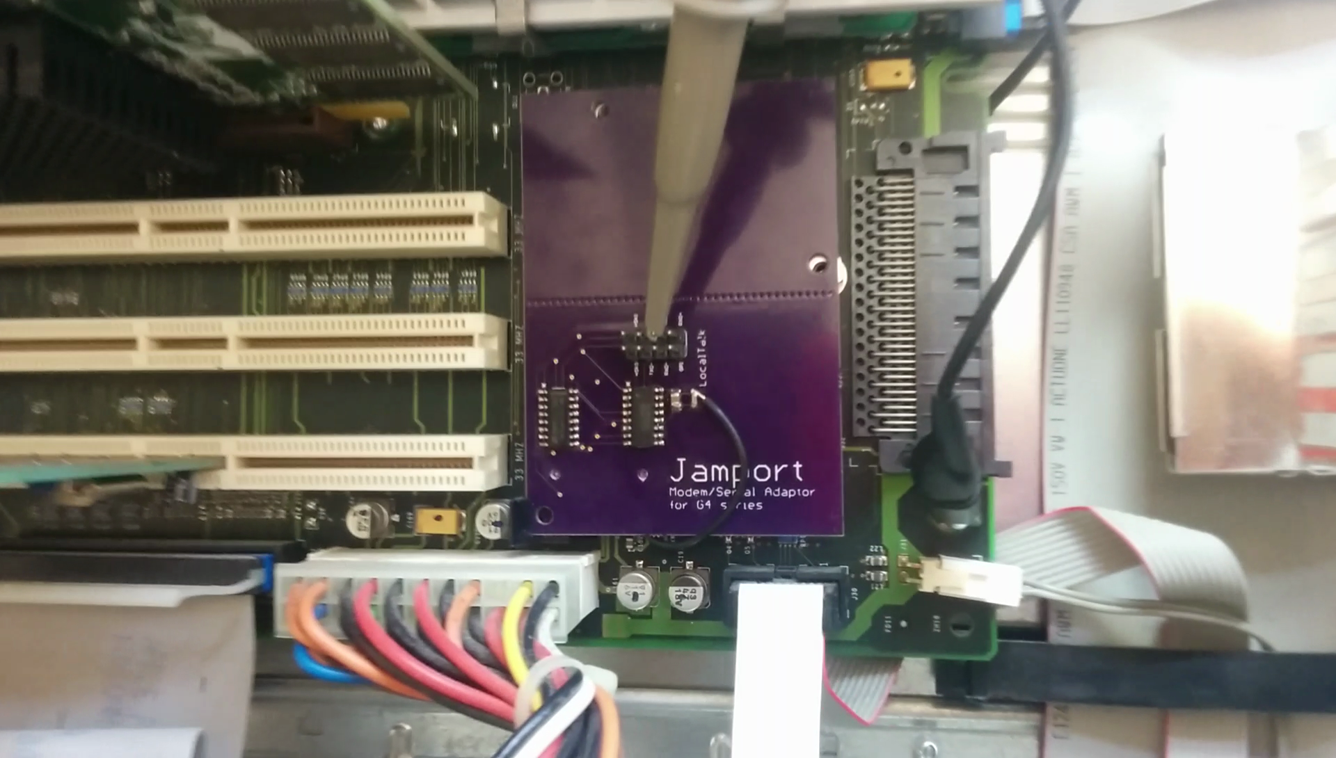
The Jamport doesn’t any of those ICs; it uses individual RS422 drivers and receivers. The reason was, I think, because in bulk the single-chip solution cost more than the cost of individually buying the driver/receivers. I also wasn’t sure about their future life cycle status — yes, they’re listed as Active, but realistically, how many people need RS422 drivers compared to GeoPort transceivers? I would presume RS422 would be used in many more applications.
On the Jamport, the driver and receiver are basically are wired up per the “Typical Application Information” diagram on page 7 of the DS8925 datasheet.
Software
OS X
From what I can see, both manufacturer’s OS X driver is simply a compiled version of Apple’s AppleSCCSerial module, with their own licenses slapped onto it.
Apple provides the source code tarballs to this driver through their Apple Open Source programme. There is an unofficial Github mirror here if that’s useful.
OS 9
Similarly, I suspect the OS 9 drivers are just Apple’s serial debug drivers. However, I don’t know where the source comes from, so I can’t compile my own versions and provide those.
Modem Connectors
Position count is the total number of pins. Thus, say we have a 20-pin, 2 row connector. Then there are 2x10 pins total pins.
| Name | Pin Count | Serial Support | Models | Notes |
|---|---|---|---|---|
| Dash? | 2x35 = 70 | Yes | iMac G3, Power Mac G3, Power Mac G4 (PCI Graphics) | Don't know pinout yet, but guessing pins 1-14 are the same? |
| Dash II | 2x20 = 40 | Yes | iMac G4, Power Mac G4, all except PCI Graphics | Used by Jamport G4 |
| MicroDash | 2x15 = 30 | Yes | iBook, iBook (Opaque 16 VRAM), iBook (32 VRAM), iBook (800/900 MHz) | On newer devices, the first half of this connector may be connected to GND (in case of Q52) or I2S bus, rather than SCC |
| Q52 | 2x15 = 30 | No | iMac G5? | Modem connected to I2C bus. Based on Intel Mobile Audio/Modem Daughter Card Specification |
| USB Modem/Soft Modem | 2x8 = 16 | No | Powerbook G4 15", 17", iMac G5? | Provides I2C and USB buses. Powerbook has 2x5 debug port, iMac need to check |
Development Photos
 The initial prototype.
 Hand-soldering the fine pitch connector was a pain. I made a breakout adapter board for my own sanity.
 Testing the Jamport with an Opcode Studio 4.
 Probing the output pins to make sure I hadn't switched TxD and RxD (again).